Ultimaker Original
The venerable UMO printer graced the team with its plywood structure and 210 x 210 x 205 mm travels (Figure P1).
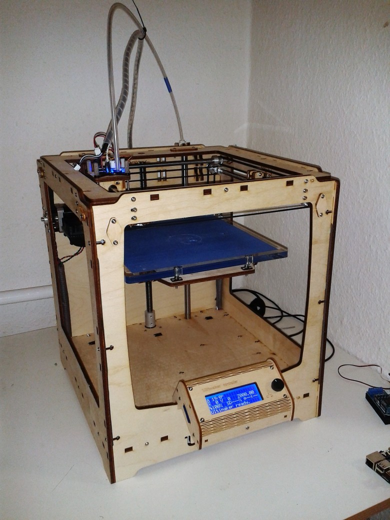
Fig. P1: Standard UMO
“UMO” is short for Ultimaker Original, which is a semi open source printer from the Netherlands (to sound cool, call it the UMO). For this project, we wanted to produce parts in not only UMO-native PLA, but also ABS. This required a heated bed upgrade in order to allow the ABS to stick to the bed, and to prevent the material from curling up around the edges as it dried. PLA and ABS are two commonly used plastic for 3D printing. PLA boasts environmental friendliness, as it is made from agricultural products, while ABS is known for being a stronger material.
The Ultimaker website explains that this 3D printer uses the Fused Deposition Modeling (FDM) method for additive manufacturing. Different 3D printing companies use different terminologies for the same type of process. This will probably continue until there is more consolidation in the industry. FDM works by laying down material through a heated nozzle (which melts the solid plastic filament into a liquid, the same as a hot glue gun) at a volumetric rate according to
Vol.dot = A * v [mm^3/s]
A = pi * r^2 [mm^2]
r = (nozzle diameter) / 2 [mm]
v = travel speed [mm/s]
We used a large nozzle diameter of 0.8 mm, and we were able to run around 60 mm/s travel. This produced, then, a volumetric flow (Vol.dot) of
Vol.dot = 30 mm^3/s = 0.03 cm^3/s.
This means that 1 cm^3 volume (1 ml) takes 1/0.03 cm^3/s = 33.3 seconds. The expectation, then, is about 2 ml volume per minute.
While the UMO Specifications list volumetric rates up to 8 mm^3/s, this was impossible with ABS, at least. With a lower volumetric flow rate, a component set for the inmoov project meant many tens of minutes, if not hours, to complete.
To get going, the first step was to make the printer function properly. Previous attempts produced poor results. In order to do this, the printer required several performance upgrades.
Heated Bed Upgrade
In order to 3D-print ABS, the team ordered and installed an Ultimaker Heated Bed Upgrade Kit.
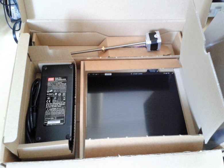
Fig. P2: Ultimaker Heated Bed Kit
This heated bed is original equipment on the UMO+. Adding this to the UMO effectively turns it into a UMO+ and enables the printing of ABS. After installation, the z-axis bearings had to be adjusted in the x-y plane so that the table could move freely up and down with minimum resistance.
The final step for the table was using the three thumb screws on the table’s underside to level it. The Ultimaker Software, Cura, v.2.3, interfaces via hardware (PC and USB cable) to the UMO and runs a calibration procedure. This procedure places the nozzle in various locations on the table, step by step, with pauses, and the operator must adjust the table position with the three turn screws. The proper spacing is achieved when a piece of paper fits between the nozzle and glass table surface. This process never required more than three attempts to level the table. The paper fit is correct when, while pulling it out, it feels “tight” against the nozzle and glass surface.
Filament Extruder
The next upgrade was the filament feeder mechanism. The UMO standard feeder is made of plywood, which is not so bad, however for better performance, a manufactured metal and robust plastic design is much better.
We choose the Titan Extruder from e3d in the UK, http://e3d-online.com/Titan-Extruder. The extruder, unfortunately, requires either a self-printed 3D bracket, or another bracket to attach it to the 3D printer. Discussion with our advisor led to a simple aluminium angle bracket that we fabricated in the lab (Fig. P3).


Fig. P3: Bracket fabrication for new Titan extruder unit
Hot End Upgrade
The final upgrade to our UMO was the hot end. This includes the nozzle, cooling fan (that blows over cooling fins) and the Bowden tube attachment. We chose an E3D-v6 set, http://e3d-online.com/E3D-v6, as we had a good experience with them regarding the Titan extruder.


Fig. P4: E3D-v6 hot end
Installing the E3D-v6 required substantial work. Fig. P4 shows some steps of the fabricating. The standard UMO 4-hole bracket needed one hole enlarged in order to fit the body section. Another L-bracket was fabricated by sawing and drilling to hold the hot end, plastic shroud and cooling fan. This final assembly was reattached to the UMO, and two stranded wires were attached back to the controller board at the bottom of the printer to power the cooling fan.
Calibration
The final step was recalibration of x and y stops, in addition to resetting the z axis 0 position. The UMO software, Cura v.2.3, includes a positioning calibration procedure. The PC is connected to the UMO via USB cable. The calibration checks the x and y stops then proceeds to place the nozzle in various locations around the table, whereby the nozzle stands still awaiting user input. During this non-movement, the user adjusts the three thumbscrews on the underside of the table until a sheet of paper barely fits between the table and the nozzle. This process continues several times in these positions. Running it one time has not been enough for proper height calibration; however, it never required more than three attempts, either.
De facto Ultimaker Original+
The final version is essentially a UMO+ with a much better feeder mechanism and much improved nozzle.
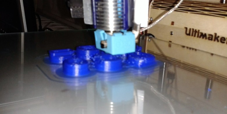
Fig. P5: E3D-v6 hot end, heated glass table
Test print
After bringing the UMO to an operable level, the next step was to test-print.
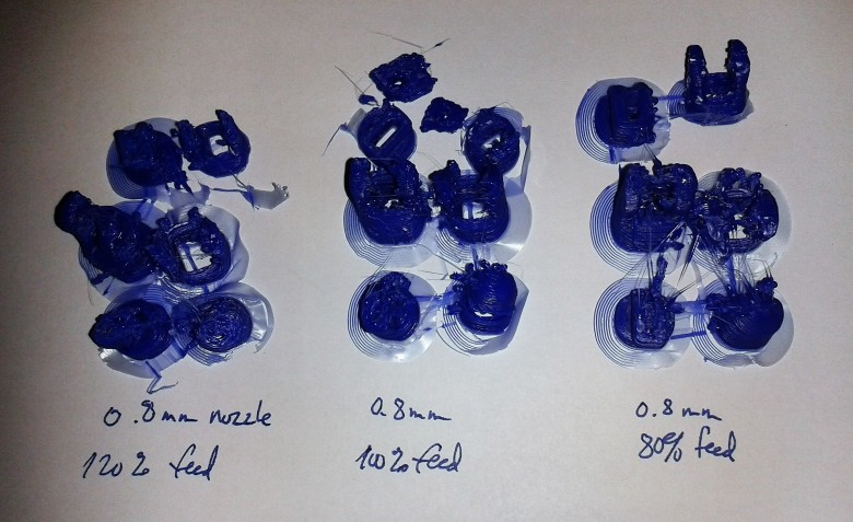
Fig. P6: Test parts at different feed percentages
There are a few basic parameters to set on the printer. They are all interconnected: for example, if the plastic is cooler, therefore “thicker”, is it not possible to extrude it through the nozzle as quickly as when the plastic is hotter, and therefore “thinner”. The rate at which the material can be extruded through the nozzle, then, relates to the nozzle travel velocity: if the nozzle travels to fast as it lays down the material, not enough material passes through the nozzle, and this causes voids in the print. The heated bed temperature is important with ABS, because when the bed is not hot enough, the material cools and peels off the glass table.
Additionally, the 0.8mm diameter nozzle was installed on the machine in order to produce parts as quickly as possible. Increasing the volumetric flow rate via larger nozzle diameter comes at the expense of surface finish, as a larger hole produces a larger bead that gets laid down on the table. It is more common to use a 0.4mm diameter, but these equations describe the time difference between the two (travel of 60 mm/minute is kept constant):
A1 (0.4mm diameter) = Pi * (0.4mm/2)^2 = 0.125 mm^2
Volumetric flow rate1 = 0.125 mm^2 * 120 mm/minute = 15.0 mm^3 per minute
A2 (0.8mm diameter) = Pi * (0.8mm/2)^2 = 0.502 mm^2
Volumetric flow rate2 = 0.502 mm^2 * 120 mm/minute = 60.2 mm^3 per minute
This is a volumetric flow rate difference of 4x! This translates into a massive time difference in producing the parts. Estimates for components ranged from 2 hours to 8+ hours when using the 0.4 mm diameter nozzle. Using the 0.8 mm nozzle reduced these to 30 minutes to 2 hours. As time was critical, and surface finish was not, the correct decision was to produce material as quickly as possible, hence the 0.8 mm diameter.
With these relationships in mind, the initial settings were set with the parameters:
- Heated bed temperature: 90ºC
- Nozzle temperature: 230ºC
- Nozzle travel velocity: 120 mm / minute
- Extrusion flow: 100%
It is possible to adjust these parameters on-the-fly via the controller.
Figure P6 show initial ABS 3D Printing results at feed percentages of 120%, 100% and 80%. The feedrates are automatically calculated by Ultimaker’s Cura® software package. The percentage of the calculated feedrate is simply 120% of the extrusion mm/time, for example, and these were percentages of 120%, 100% and 80% were adjusted on the controller panel while printing. The prints at different extrusion rates did not produce significantly different results.
Further testing showed mixed results. Sometimes parts stuck well to the heated bed, sometimes they did not. The higher the nozzle temperature, the higher the filament can be extruded — at least in theory. The nozzle travel velocity was well within the UMO’s velocity limits.
The feeder was making a strange grinding-like noise from time to time. Disassembling the extruder mechanism showed that its parts were in good order and not broken. The filament, however, appeared to be a bit chewed-up. This can happen with the knurled part of the extruder tries to push the filament, but instead grinds it up.
While running another print, the operator put his hand on the protruding gear mechanism, and felt that the gear was not turning while it made the noise. By turning the gear with his hand, while the print was running and the extruder was trying to feed the filament, it was possible to continue to advance the filament through the heated nozzle. Further inspection and testing of the feeder mechanism revealed that while the filament was getting ground up, the noise was not from this, but rather from the stepper motor as it tried to advance but could not. This resulted in the stepper moving rapidly in the forward and reverse directions which caused a grinding-like noise.
The only way to reduce this forward and backward movement was to reduce the nozzle travel velocity. The reason for this is that additional nozzle temperature started to turn the ABS brown: it started to burn it. Reduced the extrusion rate caused additional voids in the printed material, as for the given nozzle travel velocity, not enough material was extruded. The nozzle velocity had to be reduced to around 60 mm / minute in order to reduce the extruder stepper motor noise down to an occasional grinding sound.
Another issue was that the material would peel from the heated bed. The bed temperature was increased from 90ºC to 105ºC, and this problem did not appear again.
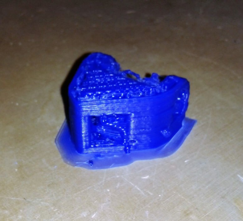
Fig. P7: Finger joint
Serial part production
With the parameters dialed-in, the UMO produced nice quality 3D printed parts. Figure P6 shows part of the finger joint. It is not possible to cutoff the extruded material flow during printing, and this is the reason for the droplets that appear in the front of this part. They are easy to remove with a knife.
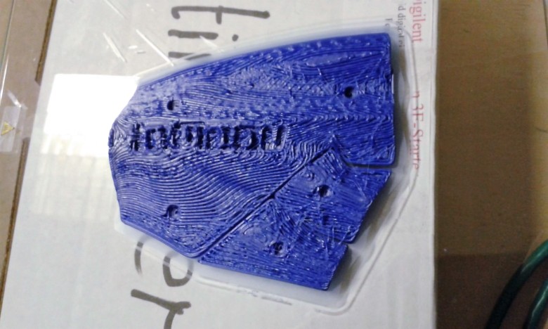
Fig. P8: Hand cover
Continuing the printing produced more and more good parts. Figure P8 shows the hand cover. The effect of the large 0.8 mm diameter nozzle opening shows through the stratified surface.
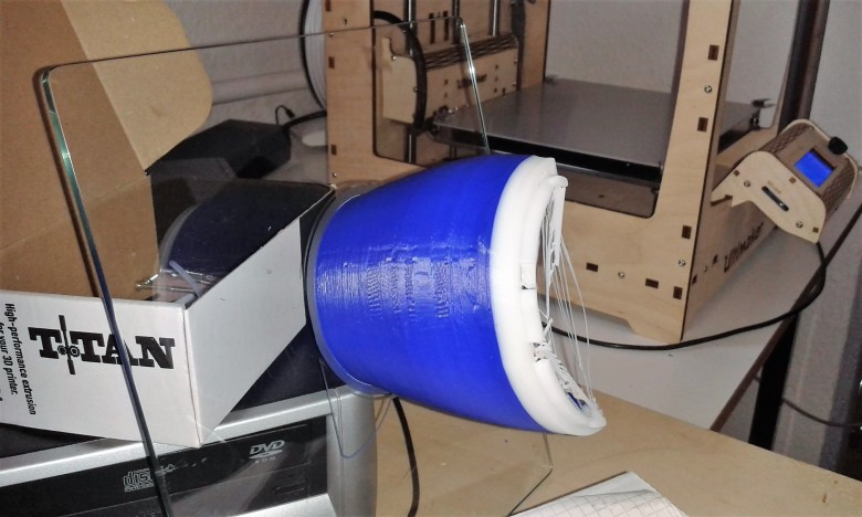
Fig. P9: Forearm component
After printing many components, fingers, thumbs, the hand, the blue 3 mm filament ran out near the end of a forearm component print. Fortunately, it was possible to follow the blue material with a new white material and finish the part in two tone blue and white. Figure 9 shows this component, still attached to the heated glass plate from the heated bed. The glass had to cool before the parts could be easily removed from it.
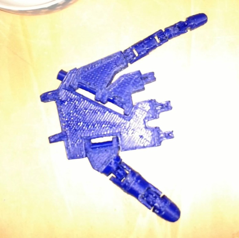
Fig. P10: Assembly
After most components were printed, the fingers had to be adhered to make individual segments. Since the material is ABS, acetone is an easy solution to melt both sides of the material and stick is together (solvent weld). This process is straightforward and appears to make strong joints. Figure 10 shows the pinky finger and thumb along with the main hand components.
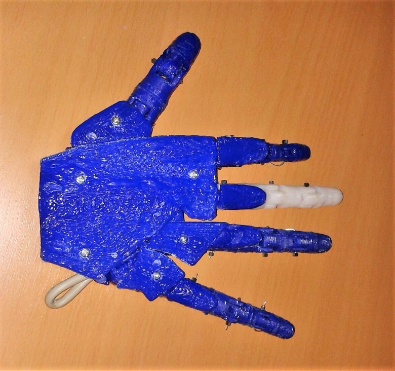
Fig. P11: Assembled hand
The assembled hand was temporarily pinned with 1 mm electronics connectors and a piece of wire. Figure 11 shows this fit-up state.
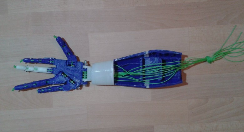
Fig. P12: Assembled hand with forearm and tendons
The final 3D printed assembly is a combination of the hand, wrist and forearm. The forearm carries the bracket for the servomotors. For servomotors, see TUTORIALS >> MOTORS.
To control the motors, myosensors and Arduino are implemented, see TUTORIALS >> ELECTROMYOGRAPHY.
