Muscle Control
Overview
This tutorial will cover Electromyography (EMG) muscle sensors to control the open source Inmoov hand. The MyoWare Muscle Sensor Development Kit was purchased for the purpose of this project Shop.
You will need:
- 1 x MyoWare Sensor
- 1 x MyoWare LED shield or 1 x MyoWare Power Shield
- Micro USB (to charge LED shield)
- 1 x Arduino Uno (or similar model)
- Computer running Arduino IDE
- 3 x sticky electrode pads
- soldering iron + solder
- 8 x Stackable Header- 3 Pin Female
- 1 red wire
- 1 black wire
- 1 white wire
Optional:
- 1 Electrode Cable
- 2 CR 2032 coin cell batteries
- Cable Shield
- Power Shield
- Proto Shield
Documents:
The MyoWare Sensor
Electromyography (EMG) sensors are used to detect electrical potentials from a summation of muscle fibers under the skin. Sticky skin electrodes receive this electrical activity, which is then passed through a series of amplifiers and filters to produce a clean signal. This signal is then passed through the Arduino Uno’s Analog To Digital Converter (ADC). The stronger the muscle flexion, the greater the signal output will be for the control of the PWM motors Motors.
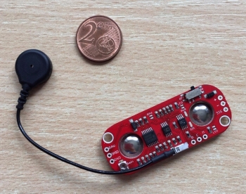
Fig.1: MyoWare sensory from Advancer Technologies
The MyoWare sensor combines all EMG hardware components into one simple design from Advancer Technologies.
Power Supply
To create a design without a USB power source, you will need a power supply for the MyoWare Sensor. For this purpose, two Power shields are included in the Kit, a Power Shield, and a LED Shield. The Power Shield takes two standard CR2032 coin cell batteries, while the LED shield uses a lithium polymer battery to charge the MyoWare sensor.
WARNING: While both shields provide power, they operate at slightly different voltages. Therefore, they should not be used at the same time!
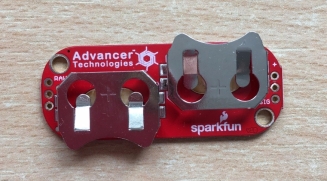

Fig. 2: Power Shield and LED Shield from Advancer Technologies.
In addition to being a power source, the LED shield has a ten segment LED display. The more muscle activity measured, the more LED bars light up along the device!
Connectors
Stackable female headers are used to connect the LED Shield, power shield, or cable shield to the MyoWare Sensor.

Fig. 3: Male and Female Header connectors
A soldering Iron and solder are used to connect the headers to the shield pins in the correct configuration for signal transmission.
Arduino Uno
The Arduino Uno Microprocessor was chosen for its simplicity and ability to cover all functions of this project. This is an 8-bit microcontroller based on ATmega328P specifications. The MyoWare sensor is compatible with the Arduino Uno hardware and can be connected to any of the Arduino’s 6 analog input pins, 3.3 and 5 V power supply pins, and ground pins.

Fig. 4: Arduino Uno connected to a computer with USB cable.
Arduino- MyoWare Set-up
The MyoWare muscle sensor (AT-04-001) datasheet shows four different setup configurations, with the recommended setup shown below. If the battery is connected directly to the MyoWare sensor, an isolation amplifier is necessary to protect the user. Otherwise, it is fine to connect the MyoWare’s positive voltage supply pin to the 5V pin on the Arduino Board and attach a battery to Vin and Ground on the Arduino Board. The MyoWare sensor should also be grounded by attaching the negative voltage supply pin to the ground pin on the Arduino Uno.
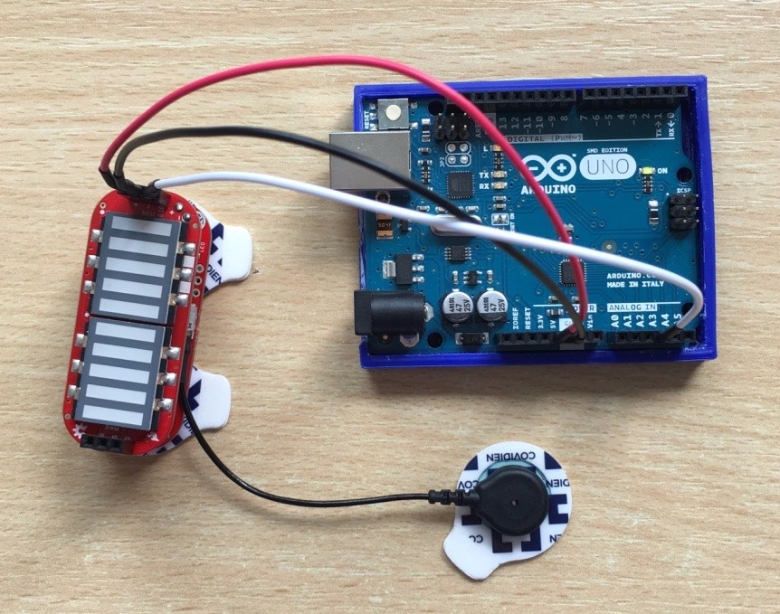
Fig. 5: MyoWare & Arduino Uno Setup
The processed muscle signal (rectified and integrated) from the MyoWare Sensor is connected to one of the analog pins on the Arduino Board from the MyoWare’s ‘SIG’ pin. The MyoWare output signal correlates to the amount of force developed in the selected muscle. As the muscle group flexes, the sensor’s output voltage increases, and the MyoWare’s signal light flashes. This analog EMG signal can then be read by Arduino’s ADC. The digital values produced can then be used to control the PWM motors to open and close the prosthetic hand.
Preparing the Sensor Electrodes
Disposable electrode pads can be used to measure, EEG, ECG, and EMG levels. These pads are perfect for short-term monitoring of EMG and hence why we used them! Each pad contains integrated gel and adheres very well to the skin. Moreover, their snap connector can be pushed on or removed from the MyoWare sensor with no issue.

Fig. 6: Disposable Biomedical Electrodes
Before placing electrode pads on the skin, it is recommended to clean and remove all dirt and oil that would otherwise impede the EMG signal!
Positioning the Electrodes
Correct electrode positioning and orientation are essential for proper strength and quality of the EMG signal. The electric potential difference is measured along the length of the muscle fibers with one electrode placed in the center of the muscle and the other electrodes placed at the end of the muscle group. This positioning ensures the detection of a higher number of muscle motor units.

Fig. 7: MyoWare Sensor placed on the bicep muscle.
The reference electrode is placed on any non-adjacent muscle group to prevent any interfering signal.
Uploading Test Firmware
The MyoWare Sensor Test code from OpenBionics can be used to verify the MyoWare sensor is wired and connected to skin properly.
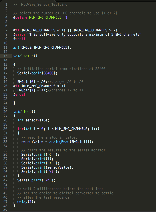
Fig. 8: OpenBionics Test Code
Using the Sensor
The image below depicts the motion needed to activate the bicep muscle. And ‘L’ positioning + clenching of the fist should be performed until you see/feel the muscle underneath the MyoWare board tense.
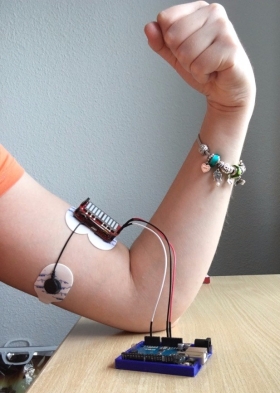
Fig. 9: Hand motion for muscle activation
Other muscle groups can also be activated for this application, using other positions/gestures.
Turning the Gain
When the muscle is relaxed, the ADC value should read around 0-300, and when the muscle is tensed it should rest around 700-900. If the ADC value is too low, you should adjust the gain on the MyoWare sensor.
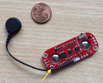
Fig.10: Sensitivity adjustment.
Use a flat-head screwdriver to increase the gain by turning clockwise.
Connecting External Electrode Cables
Instead of attaching the MyoWare sensor directly to the muscle, use the three-electrode cable connected to the cable shield (shown below). Attach electrodes to the three cable ends, making sure to only use one pad for each (Reference, End, and Middle).
Middle:
Connect the middle electrode pad in the middle of the muscle body
End:
Connect the end electrode pad towards the end of the muscle body
Reference:
Connect the Reference electrode pad on a separate section of the body, such as elbow or another muscle group

Fig. 10: Middle and End electrode placement.

Fig. 11: Reference electrode placement.
If the cable shield is used, solder the Reference, End and Middle pins for both the cable shield and the MyoWare Sensor. Otherwise, external cables can be connected to the three pins on the MyoWare sensor shown in Fig. 13.
The cable shield should be stacked directly on top of the MyoWare board, as the LED and power shields do not have the Reference, End, and Middle pins.

Fig. 12: Three-Electrode Cable and Cable shield

Fig. 13: Soldering needed when connecting external electrode cables.
The Power Shield
The power shield for the MyoWare sensor is designed to take two standard CR 2032 coin cell batteries. The are connected in parallel for a capacity at nominal 3.0V. Battery Power also provides a cleaner signal and eliminates the chance of dangerous current paths.

Fig. 14: Power Shield (Top View)
Proto Shield
The Proto Shield can be used to solder on custom circuitry.

Fig.15: Proto Shield
The Cable Shield and Proto Shield have two rows of 3-pin holes on each end allowing them to be stacked with other boards. The outer row on the top can also be used to stack another shield on top for a total of 4 boards in a stack.
MyoWare Sensor- Arduino Programming
Picture of Final Program
#define NUM_EMG_CHANNELS 1
Description
This software supports 1 EMG channel, however, 2 or more can be added depending on your application.
void setup()
Description
The function is called when the Arduino sketch starts and initializes variables, libraries, etc. only once.
Serial.begin(38400);
Description
This line sets the bits per second (baud) for serial data transmission. Other Baud rates can be selected. See Serial Begin for more.
void loop()
Description
The loop function loops continuously, allowing for active control of the Arduino board.
analogRead(EMGpin[i]);
Description
This reads the value from a specific analog pin on the Arduino board. The Arduino Uno contains 6 analog channels and a 10 bit analog to digital converter. The 10-bit conversion means it maps input voltages between 0 and 5 V into integer values between 0 and 1023. This results in resolution readings of 4.9mV per unit. Therefore, if the test program outputs 16, this value can be multiplied by 4.9mV to give the potential detected by the MyoWare sensor.
Serial.print()
Description
This command prints readable text characters to the serial port/monitor. Any data type can be printed, for example, the text will be printed if it is encased by quotations (” “) while variables in the program are printed by including the variable name.
delay(2);
Description
This allows for the analog- to- digital converter to settle after the last reading; waiting for 2 milliseconds before the next loop (there are 1000 milliseconds in a second).
Threshold Value
After testing our MyoWare sensor in conjunction with bicep muscle flexions, a relaxed state resulted in an ADC value around 400, and when the bicep muscle is tensed it rests around 700-900. The comparison operators: less than (<) and greater than (>) in combination with these threshold values are used to set the motor positions are various angle positions.
